A forged component can have the required strength, but if its dimensions are incorrect, it may not function correctly in the final assembly.
In heavy engineering, power transmission, automotive drivelines, defence, and aerospace applications, component integrity is evaluated across two inseparable fronts: metallurgical integrity and geometric accuracy. While open die and closed die forging deliver superior continuous grain flow, fine microstructures, and outstanding tensile and fatigue resistance, the component must ultimately fit into an intricate assembly where clearances are measured in hundredths of a millimeter. Even an exceptionally strong forging will cause operational failure or costly assembly line stoppages if critical dimensional tolerances are compromised.
What Is Dimensional Accuracy?
Dimensional accuracy defines the degree of conformity between the physical measurements of a manufactured component and the exact specifications, limits, and tolerances laid out in the engineering drawing.
Critical dimensions in forged and machined engineering components include:
Diameter
Outer diameters (OD), inner bore diameters (ID), bearing journal fits, and stepped transition diameters that dictate press-fit, clearance-fit, or transitional-fit assembly interfaces.
Length
Overall part lengths, step-to-step shoulder distances, flange axial spans, and spline engagement lengths essential for proper axial shaft locating and gear mesh alignment.
Thickness
Wall thickness uniformity in forged seamless rolled rings, flange hub cross-sections, and rectangular block heights required to withstand internal pressures and mechanical bending moments.
Hole Dimensions
Bore concentricity, hole diameters, pitch circle diameters (PCD), thread pitch, counterbore depths, and reamed pin holes that govern bolted flange connections and precision alignment dowels.
Geometric Features (GD&T)
Geometric dimensioning and tolerancing parameters—such as circular runout, total runout, perpendicularity of shoulders, parallelism of block faces, and concentricity across stepped shaft journals.
Surface Requirements
Surface roughness values (Ra, Rz), sealing face finishes, groove profiles, and micro-inch surface lay that dictate gasket sealing reliability, fluid containment, and hydrodynamic bearing lubrication.
Machining Allowances
Controlled stock envelopes left on rough-forged blanks to ensure that subsequent proof-machining and final finish operations completely remove surface oxidation and decarburization without cutting undersize.
Forging and Machining: The Complementary Relationship
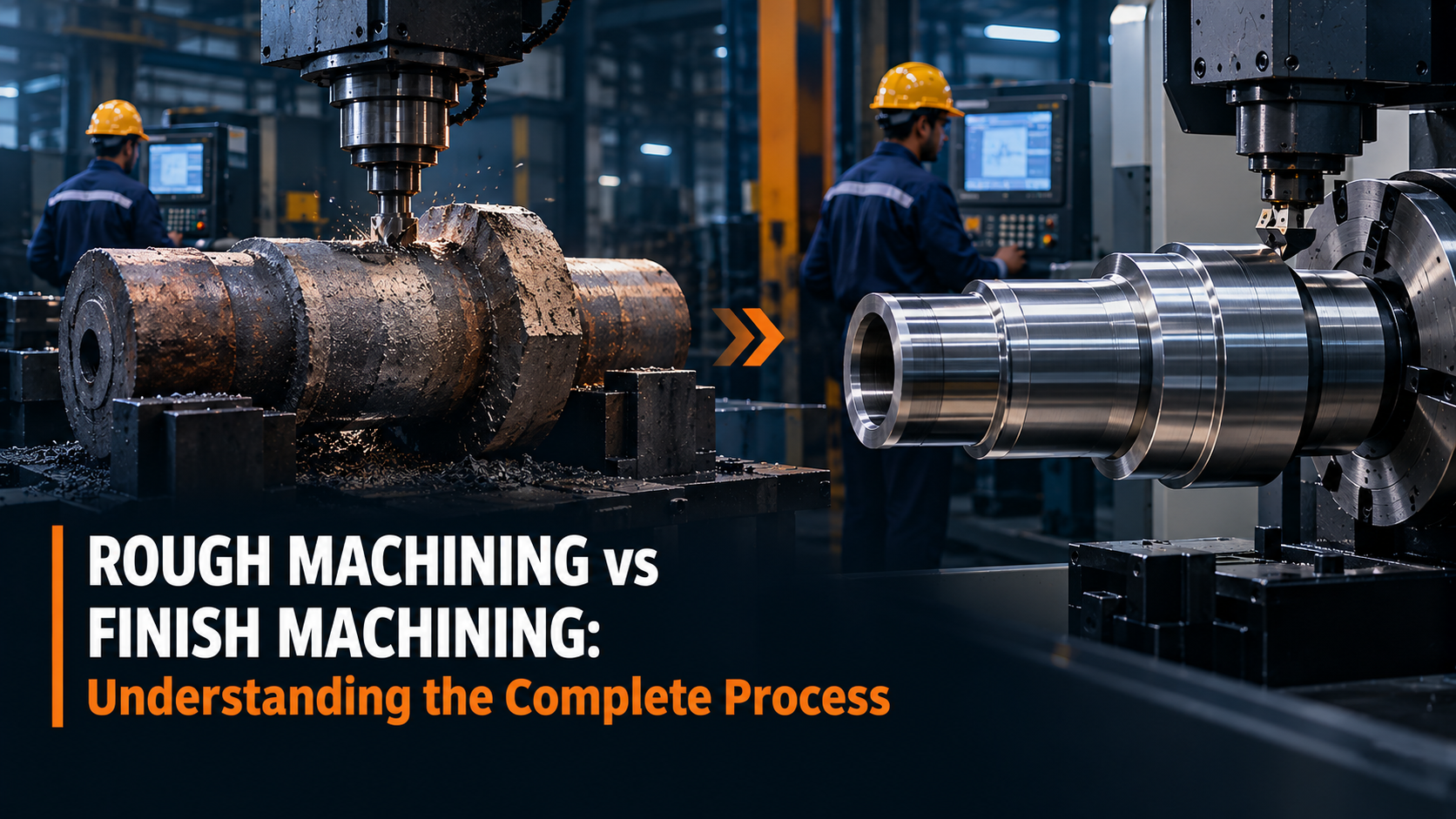
Forging establishes the basic component geometry, while machining can bring critical features to the required final dimensions.
Achieving micron-level accuracy begins long before the part reaches the CNC machining center. During hot open die forging, pneumatic hammers shape steel billets at temperatures between 1050°C and 1250°C. Due to thermal expansion, oxide scale formation, and hammer tool dynamics, open die forgings are produced with intentional dimensional allowances (typically 3 mm to 10 mm of sacrificial stock per surface depending on ruling dimensions). This envelope guarantees that the dense, void-free forged grain matrix fully covers the target component geometry.
| Manufacturing Stage | Typical Tolerance Range | Surface Roughness (Ra) | Primary Function |
|---|---|---|---|
| Open Die Forging | ±2.0 mm to ±6.0 mm | As-forged skin with scale | Creates basic geometry; consolidates internal voids; imparts unbroken grain flow. |
| Rough / Proof Machining | ±0.5 mm to ±1.5 mm | Ra 6.3 µm to 12.5 µm | Removes scale/decarb; enables 100% volumetric Ultrasonic Testing (UT); relieves bulk stresses. |
| Finish Precision Machining | ±0.01 mm to ±0.05 mm (IT6–IT8) | Ra 0.8 µm to 3.2 µm | Achieves exact nominal dimensions, GD&T relationships, fine sealing finishes, and functional features. |
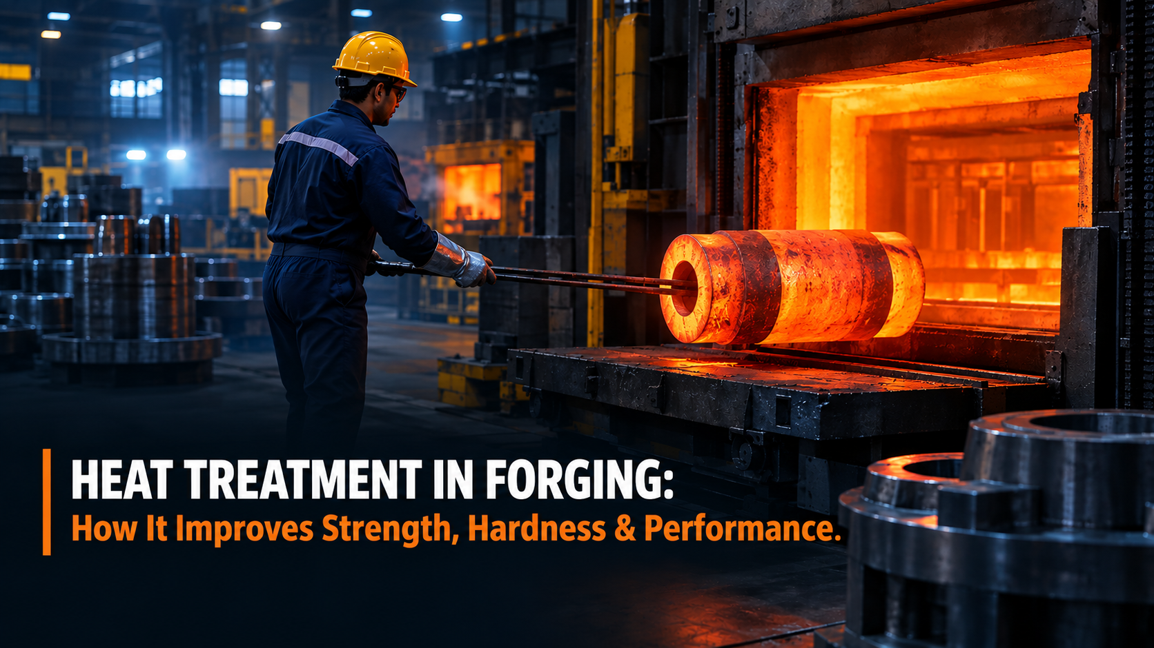
Following thermal normalization or quench-and-temper (Q&T) heat treatment, the component undergoes finish CNC machining. Precision turning centers, vertical boring machines, and multi-axis milling machines cut the final profiles without inducing thermal distortion or altering the underlying metallurgical properties.
Inspection: Verification and Metrology
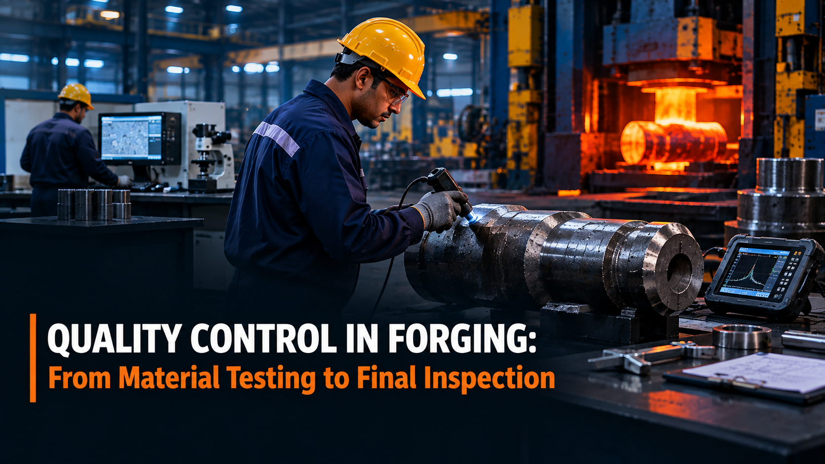
Dimensional inspection verifies whether the finished component meets the specified drawing requirements.
Inspection is not merely a post-manufacturing checkpoint; it is a continuous quality control protocol embedded into every manufacturing phase. At Forgewell Industries, dimensional verification utilizes calibrated precision metrology instruments:
- Digital & Vernier Calipers and Outside Micrometers: Multi-point diameter and length measurements across journals, steps, and outer profiles to verify tolerance compliance down to 0.01 mm.
- Three-Point Internal Micrometers & Bore Gauges: Validating inner diameter concentricity, roundness, and bore taper across forged hollow sleeves and rings.
- Height Gauges on Precision Granite Surface Plates: Verifying axial steps, perpendicularity of shoulders, and block parallelism in controlled measurement environments.
- Coordinate Measuring & Optical Profile Verification: Evaluating complex geometric dimensioning and tolerancing (GD&T) relationships such as runout, true position, and angularity.
- Thread Gauges & Go / No-Go Plug Gauges: Fast, foolproof verification of critical internal/external threads and keyway slot widths to eliminate assembly mismatch risks.
Why It Matters: The 5 Pillars of Dimensional Accuracy
Dimensional accuracy helps ensure:
1. Proper Assembly
Industrial equipment relies on interference fits, slip fits, and precise keyways. When dimensions are accurate, shafts slide smoothly into bearings, couplings mate securely without force, and gear teeth mesh at exact center distances without binding or galling.
2. Functional Performance
Even minute runout or out-of-roundness on a rotating shaft induces dynamic imbalance at high operational speeds, causing severe vibration, excessive bearing friction, elevated operating temperatures, and premature component fatigue.
3. Interchangeability
Modern global supply chains require 100% component interchangeability. A forged replacement shaft or ring supplied today must fit identically into an assembly built five years ago without needing on-site grinding, shimming, or custom modifications.
4. Reduced Rejection & Lower Lifecycle Cost
Strict in-process dimensional control prevents components from being machined undersize—the primary cause of unrecoverable scrap. Catching deviations early saves expensive machining hours and avoids costly supply chain delays.
5. Consistent Production
Repeatable dimensional precision gives OEM buyers total confidence across recurring production batches. Every shipment meets the same stringent drawing requirements, guaranteeing predictable assembly times and flawless field uptime.
Forgewell Approach
Forgewell combines controlled manufacturing processes with inspection to deliver components according to customer specifications.
At Forgewell Industries, dimensional accuracy is engineered directly into our single-roof manufacturing ecosystem. By unifying open die forging (pneumatic hammers up to 1500 kg capacity), rough proof-machining, certified heat treatment, and precision finish machining in Pune, our engineering team maintains unbroken traceability and process control over every millimeter of material removal.
Whether producing stepped shafts up to 800 mm in diameter, rolled rings, forged discs, or square blocks, each piece is accompanied by comprehensive Inspection & Test Plans (ITP), dimensional inspection reports, and full material test certificates (EN 10204 3.1).
Precision is not an option when components must fit, function and perform.